|
Industrial Wireless Radio Controls
Specification
Data
|
Performance |
Migro
Extended Range |
• 5 miles (10 km)
line-of-sight w Omni antenna
• Extended range up to 20 km
• MTX48 FM
Power Pulse System
•
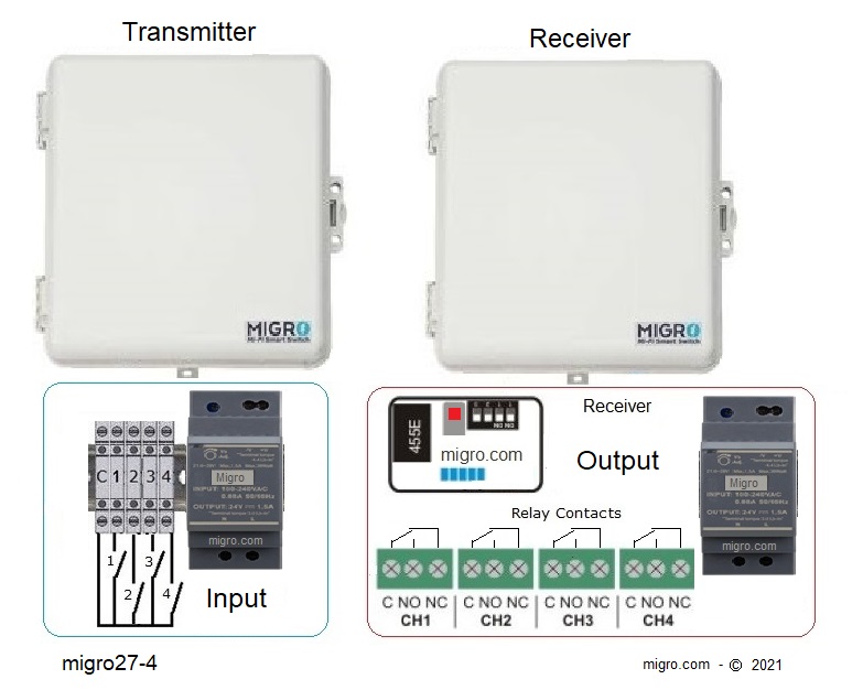
Transmitter input N/O Dry contact
• Relay Output SPDT, 10A @250VAC
Class 2
• Momentary or Pulse Output for each channel
•
Heavy Duty Weatherproof, IP65 enclosure
• License free operation
at the Industrial band
• Factory configured systems, Ready to operate
• Simple setup & programming without
a PC
• Not limited to line-of-sight
communication
■
Request a
Quotation |
|
4
Channel
Transmitter and Receiver
915404 System 4 Channel
915414 Receiver 4 Channel
915424 Transmitter 4 Channel
Operation Selection:
120/240VAC,12VDC,
915404 include:
One Base
Transmitter, One Base Receiver
Two 931487 Omni Antennas with coaxial cable,
Weatherproof Enclosures &
Instructions |
.
| Supply power |
120/240VAC or
12VDC / 5watt |
|
Inputs |
N/O Normally
Open, digital dry contact |
| Transmitter power |
per
FCC Part 15.249,
50mV/m @ 3m (Power-Pulse) |
| Transmitter current |
Standby 0.1mA, Transmission 240mA |
| Transmission |
Digital Encoded
Gaussian_frequency-shift_keying |
|
Channels |
16 addresses per system
GFSK |
|
Input Wiring |
Din Terminals,
Dry Contact |
| Response |
Loop 500 msec
|
| Weight |
2 lb (1.40kg)
each unit |
| Dimensions* |
9"W x
9"H x
4"D (230 x 230 x 100 mm) |
|
Specifications
Digital Receiver 915414 |
| Supply power |
120/240VAC or
12VDC / 5watt |
|
Output |
Relay 10Amp, Class 2 pilot duty
SPDT |
| Frequency |
VHF 154 MHz • License free MURS band |
|
Configuration |
DIP switch factory
preset |
|
Compliance |
FCC CFR part 15.247, 95 sub E |
|
Wiring |
Screw Terminals |
| Antenna Z |
50 Ohm, SO-239 |
| Ambient temp |
14° to 140° F (-10° to 60°
C) |
| Enclosure |
Weatherproof, IP65 |
|
Transmission Mode
|
Special
Options:
|
|
■
Continuous
(1)
■ Off Delay Timing
■ Pulse Output
■ Latching
for each
channel
|
■
Fail Safe sequence module
■
Battery Backup module
■ Repeaters and extended range systems
■ High, Low Status level indicator lamp
■ Automatic Start/Stop module
|
|
(1)
FCC
Part 95,
subpart B |
|
|
Compliance:
MIL-STD-461E
for
Electro-Magnetic
Interference
(EMI)
MIL-STD-901D
Grade A for High
Impact Shock
MIL-STD-167B
for Vibration |
Please
Request latest price
-
Antenna Range Calculator
|
|
Long
Range Wireless Systems
The potential range is
approximately 5 miles*
with proper antenna
application, is not limited to line of sight. |
 |
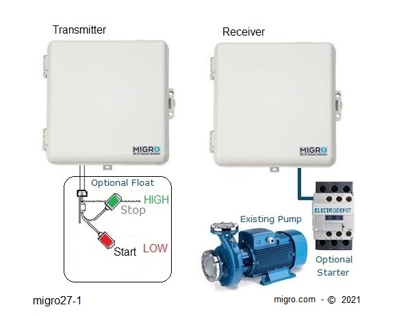
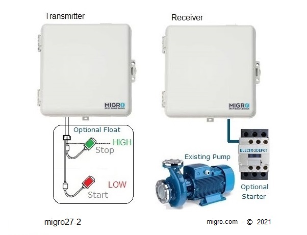
■
Applications:
Industrial Monitoring, Pump control, Monitor remote
sites, Tank Level,
Lighting control, Remote Mobile system, PLC remote, SCADA,
Gates.
Factory process control, Alarms, Generators,
Solar, Wire replacement.
Please
request a quotation
|
|
Single Channels Application Example |
|
|
2 Channels Application Layout |
 |
•
|
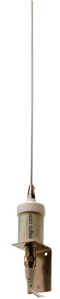
150MHz
2 Meter
Omni Antenna
( 5/8 )
|
Transmission Pattern
Additional Antenna Selection |
| Frequency |
140-170 MHz |
| Gain |
4.5 dBi |
|
Overall Length |
37 inches |
| Impedance |
50 Ohms |
|
Connector |
SO-239 |
| Max Power
|
150 Watts |
| VSWR
5MHz |
<
1.5:1 avg. |
| Polarization |
Vertical |
| Wind Data |
150 mph |
12 Feet of 50 ohm coaxial cable,
|
.. |
|