| |
Industrial Wireless Long Range Radio Controls
 |
Applications:
Industrial Monitoring, Pump control, Monitor remote
sites, Tank Level,
Lighting control, Remote Mobile system, PLC remote, Irrigation, Gates.
Factory process control, Traffic management and Signaling,
Flood control, Perimeter protection, Alarms, Generators, Marinas, Solar
systems, Wire replacement. |
|
|
Heavy Duty Extended Range
M154 Radios
|
... |
OEM Components
|
|
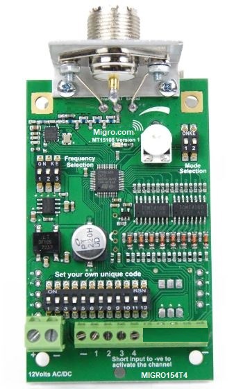
TRANSMITTER 4CH |
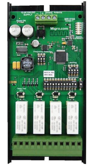
RECEIVER 4CH |
 |
 |
|
|
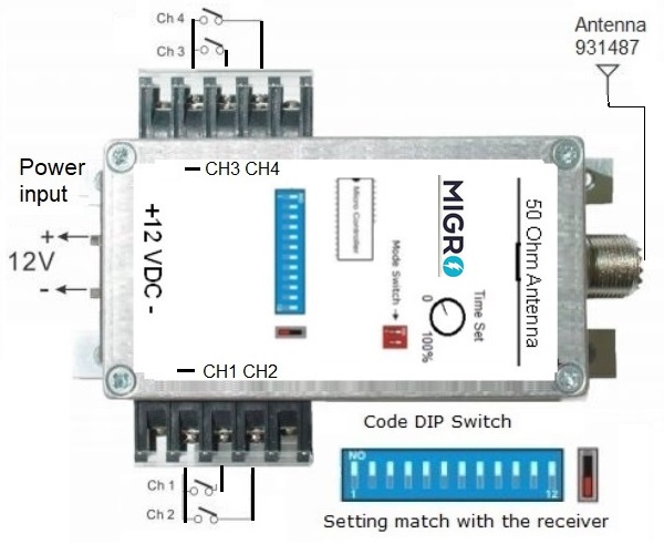
Wiring
and Setup
|
Request
OEM Price |
| |
|
|
Specifications
MIGRO154T4 Digital Transmitter
|
| Supply power |
12VDC / 8Watt |
|
Inputs |
N/O Normally
Open, digital dry contact |
| Transmitter power |
per
FCC Part 15.249,
50mV/m @ 3m |
| Frequency |
154MHz •
License free MURS band |
| Transmission |
Digital Encoded
Gaussian_frequency-shift_keying. |
|
Channels |
16 addresses per system
GFSK |
|
Power draw |
Standby 1mA,
Transmission 1200mA Solar Ready |
| Response |
Loop 500 msec
|
| Weight |
0.70
lb ( 0.34kg )
each unit |
| Dimensions |
5x3x1 inches, 126 x 80 x 26 mm |
|
|
Specifications
MIGRO154R4
Digital Receiver
|
| Supply power |
12VDC / 5Watt |
|
Output |
Relay 8Amp, SPDT (NO/NC) Class 2 Pilot Duty |
| Output mode |
Momentary or Latching, Optional
Continuous (*) |
|
Configuration |
DIP switch factory
preset |
|
Compliance |
FCC CFR part 15.247, 95 sub E |
|
Power draw |
Standby 30mA, Full
load 400mA |
| Antenna Z |
50 Ohm, RF Connector
SO-239 |
| Ambient temp |
14° to 140° F (-10° to 60°
C) |
| Dimensions |
5x3x1 inches, 126 x 80 x 26 mm |
|
|
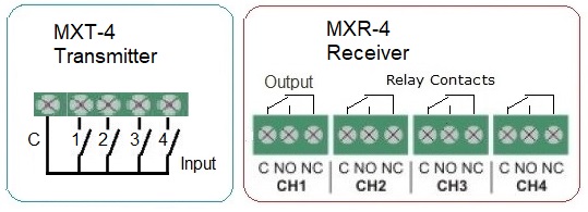
Wiring Terminals
FCC Certified
ID: OHKFMT154
COMPLIANCE: per FCC Part 15.249, 50mV/m @ 3m
Circuit board Compliance with UL796 and UL
94
MIL-STD-461E for Electro-Magnetic
Interference (EMI)
MIL-STD-901D Grade A for High Impact Shock
MIL-STD-167B for Vibration
|

|
ANTENNA
Selection 154Mhz - 50 Ohm:

Short Range |

Medium Range |

Long Range |
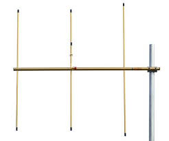
Long Range |
|
| 931501 |
931487 |
931490 |
931503 Yagi 3 Element |
|
| 2.0 dBi, 17
inch |
4.5 dBi, 37 inch |
6.7 dBi, 125 inch |
9.2 dBi, 42 inch |
|
| PL-259 |
SO-239
& 12ft Coax |
SO-239 |
SO-239 |
|
| |
|
|
|
|
Optional (*) Control Modules:
|
Fail Safe sequence mode, Modules
- NOTE
FCC Timing Compliance
OPERATION: Transmitter sends an interval pulse
as long as the input is activated by a control, switch
or sensor etc. The Receiver at the other end
turns the output ON decodes the interval to verify the
status of the transmitter, If The Transmitter Ends the control action,
or loss of power or carrier,
then The receiver decoder will acknowledge and turn the
Receiver output OFF until the controller is activated again
By Example: In a Pump Control, When
the float Sw Closes, Transmission starts, and the
Receiver activates the output Relay ON , it will
maintain these status until the Float Sw Opens, then
after the preset time (ex, 30sec) deactivates the
output Relay OFF
|
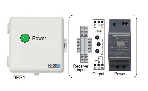
Single
channel continuous mode module (FCC Compliant)
Fail Safe sequence module, Power, Carrier
failure or end of transmission control
Comply with FCC part 15.247 sub E on Continuous
transmission timing
9FS1 Receiver
Module
Operating voltage 12VDC
Input: Dry Contact
Output: 10A SPDT
Enclosure Weatherproof IP65, 9x9x4 inches
NOTE: Transmitter or receiver not supplied,
|
 |
|
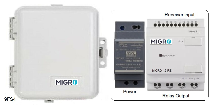
Four (4)
channel continuous mode module (FCC
Compliant)
Fail Safe sequence module, Power, Carrier
failure or end of transmission control
Comply with FCC part 15.247 sub E on Continuous
transmission timing
9FS4 Receiver
Module
Operating voltage 12VDC
Input: Dry Contact
Output: 8A SPST
Enclosure Weatherproof IP65, 9x9x4 inches
NOTE: Transmitter or receiver not supplied,
|
 |
|
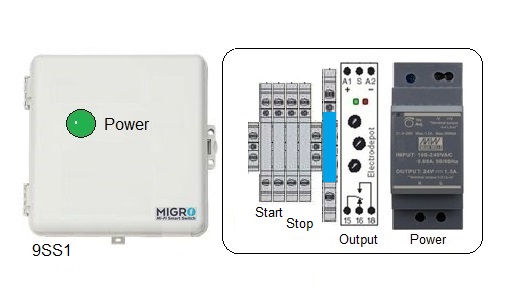
Start Stop Receiver Module
Operation:
Transmitter send a momentary pulse via Channel One (1) to
START;
the Receiver Control Module Output turns ON
It will stay
ON Until the transmitter sends the STOP signal via
Channel Two (2) to turn
the Receiver Output OFF
Start/Stop output Module
9SS1: Two input from the receiver,
One output to energize the external contactor
Operating voltage 12VDC
Input: Dry Contact
Output: 10A SPDT
Enclosure Weatherproof IP65, 9x9x4 inches
NOTE: Transmitter and receiver not supplied,
|
 |
OEM Board Selection
|
|
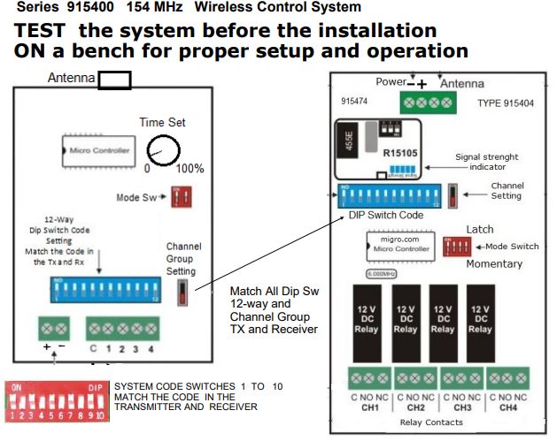
Transmitter MIGRO154T4 Receiver MIGRO154R4 |
 |
|
|
OEM Transmitter in MIL-STD Box Configuration
MIL154T4 (
Same as Board Settings ) |
|
|
|
|
 |
DISCLAIMER:
Radio control equipment
in not to be used in life safety.
Radio Installations shall be performed by a certified
professional |
NOTE
Maximum continuous transmission time per FCC: 5 minutes,
Control modules to
Comply with FCC part 15.247 sub E on Continuous
transmission timing |
|
|
|
|
Copyright © Electrodepot. All rights
reserved Rev 2024 | |