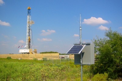
Applications:
Industrial Monitoring, Pump control, Monitor remote
sites, Tank Level,
Lighting control, Remote Mobile system, PLC remote, SCADA,
Irrigation, Gates.
Factory process control, Alarms, Generators, Solar, Wire replacement.
Extended Range
MX Modules
Performance
6 miles ( 10
Km )
line-of-sight • Extended range up to 20
Km
• Not limited to line-of-sight
communication
Up to 10 Km of line-of-sight range
with MXT4
Up to 3 Km with handheld device MXTH-4
Migro Encoding/Decoding technology Four (4) Independent Channels
Output selection: Latch or Momentary
Shielded Metal case NEMA4 - IP65
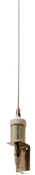
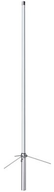
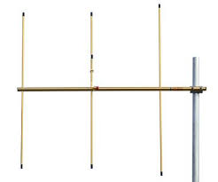
Antenna 931501 or 931487 (not
included)
Power: 12 VDC - Solar Ready
Dip Switch 12 Bit Code setting Multiple Transmitters and Receivers Optional repeater if necessary
Factory pre- configured system, Ready
No setup or programming required
No fees from carriers, No hacking
No software or internet
Specifications
Digital Transmitter
Supply power
12VDC / 8Watt
Inputs
N/O Normally
Open, digital dry contact
Transmitter power
per
FCC Part 15.249,
50mV/m @ 3m
Frequency
154MHz •
License free MURS band
Transmission
Digital Encoded
Gaussian_frequency-shift_keying
Antenna Z
50 Ohm, RF Connector
SO-239
Power draw
Standby 1mA,
Transmission 1200mA
Response
Loop 500 msec
Weight
1.12
Lb ( 0.44kg )
each unit
Dimensions
,5.76" W x2.40" H x
1.24" D
Specifications
Digital Receiver
Supply power
12VDC / 5Watt
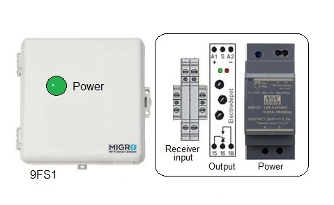
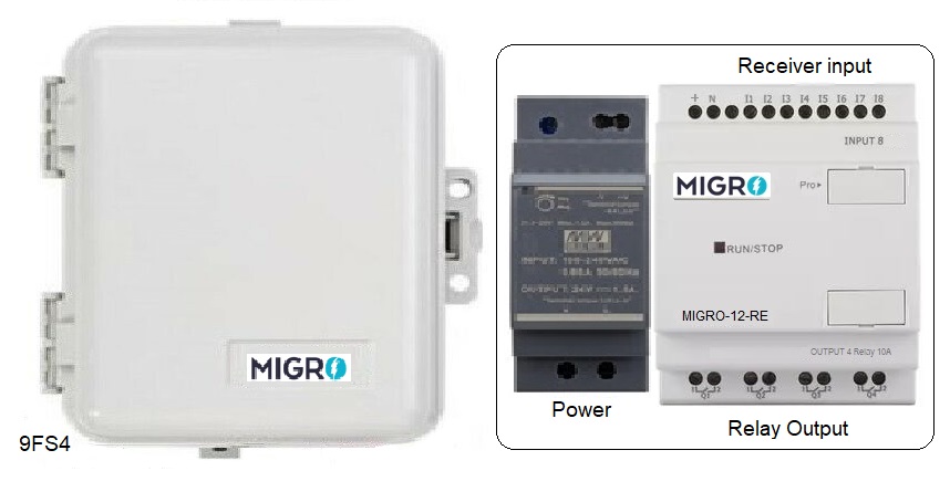
Output
Relay 8Amp, SPDT (NO/NC) Class 2 Pilot Duty
Output mode
(*) Continuous - Momentary or Latching
Configuration
DIP switch factory
preset
Compliance
FCC CFR part 15.247, 95 sub E
Power draw
Standby 30mA, Full
load 400mA
Antenna Z
50 Ohm,
Screw Terminal
Ambient temp
14° to 140° F (-10° to 60°
C)
Dimensions
3.76" W x5.40" H x1.00" D
COMPLIANCE: per FCC Part 15.249, 50mV/m @ 3m
Circuit board Compliance with UL796 and UL
94
MIL-STD-461E for Electro-Magnetic
Interference (EMI)
MIL-STD-901D Grade A for High Impact Shock
MIL-STD-167B for Vibration
OPERATION: Transmitter sends an interval pulse
as long as the input is activated by a control, switch
or sensor etc. The Receiver at the other end
turns the output ON decodes the interval to verify the
status of the transmitter, If The Transmitter,
Finalize the control action, loss of power or carrier,
then The receiver decoder will acknowledge and turn the
Receiver output OFF until the signal is activated again
Single
channel continuous mode module
Fail Safe sequence module, Power, Carrier
failure or end of transmission control
Comply with FCC part 15.247 sub E on Continuous
transmission timing
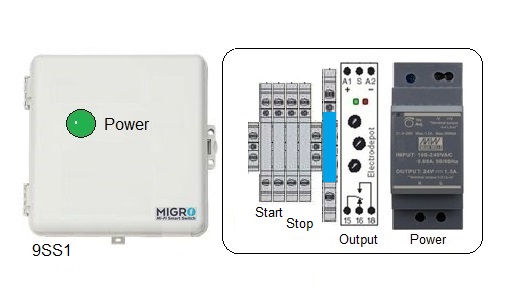
Transmitter send a momentary pulse via Channel One (1) to
START; the Receiver Control Module Output turns ON
It will stay
ON Until the transmitter sends the STOP signal via
Channel Two (2) to turn
the Receiver Output OFF
Start/Stop output Module
9SS1: Two input from the receiver,
One output to energize the external contactor
Power Adapter,
931224
AC 100-240V to DC 12V, 2A
24W Switching Power Supply
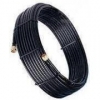
RF Cable
( Made on order )
Coaxial Cable Shielded Low Loss eff 97%
With 2x PL -259 Connectors
12Ft Coax Cable $49.99
DISCLAIMER:
(*) Maximum
continuous transmission time per FCC; 5 minutes
Radio control equipment
in not to be used in life safety.
Radio Installations shall be performed by a certified
professional